Technische Zeichnungen: Unterschied zwischen den Versionen
| Zeile 1: | Zeile 1: | ||
The process of drawing up the plans is preferably carried out in the same program in which the CAD models were created (Inventor, SolidWorks, AutoCAD...). In this program, a drawing file [.idw or similar] must be created, from which the following pdf files must be generated: | |||
[[File: | == General Pages == | ||
=== General Assembly Views === | |||
[[File:Oseg wl lacb tricycle cargo bike B-001-001.jpg|thumb]] | |||
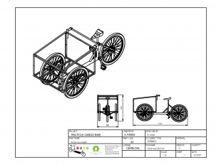
Here the project is represented in its entirety, using the appropriate scale, it includes orthogonal views, isometries, section views, detail views, general dimensions, weld details, among others, that show aspects of the assembly of the equipment in general. | |||
These views can span multiple pages, depending on the degree of complexity of the project.This section is identified with the code A1. | |||
<div style="height: 200px;"></div> | |||
* | === Single view of general explosion === | ||
* | [[File:Oseg_wl_lacb_tricycle_cargo_bike_B-002-002.jpg|thumb]] | ||
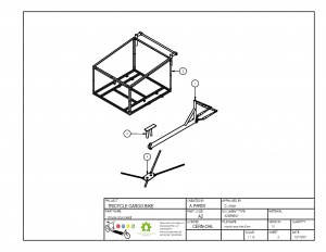
On one page, the project's main assemblies should be displayed, separated and aligned according to their assembly logic, in an isometric view.Certain common components, such as screws, pipes, connecting elements, among others, may remain in the first level of the assembly or belong to the most important set with which they are related.This section is identified with the code A2. | |||
<div style="height: 200px;"></div> | |||
=== Complete part list. === | |||
[[File:Oseg_wl_lacb_tricycle_cargo_bike_B-005-005.jpg|thumb]] | |||
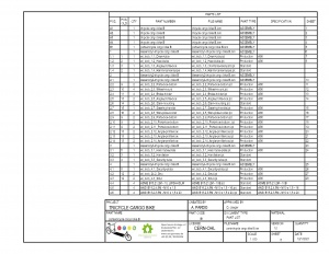
In the same format as the Technical Drawings, a table must be added with the information of all the parts and assemblies, according to their hierarchical order.all fields must be filled according to the instructions explained below.It can span as many pages as necessary.This section is identified with the code B1, B2 ..., for each page. | |||
<div style="height: 200px;"></div> | |||
.. | === Technical Notes === | ||
[[File:Tech-notes.jpg|thumb]] | |||
[[File:Tech-notes2.jpg|thumb]] | |||
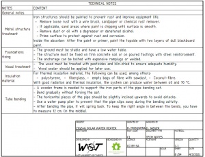
It includes all information of technical relevance, which is not practical to represent in the plans, depending on the Project, it can show the following aspects:<br> | |||
[[File:blueprint format1.jpg|thumb|<small>'''[[Media:Blueprint_format1_doc.pdf| | <br> | ||
[[File:blueprint format2.jpg|thumb|<small>'''[[Media:Blueprint_format2_doc.pdf| | |||
* Technical notes | |||
*PROJECT -> | * General technical notes | ||
*CREATED BY -> | * Standards | ||
*APPROVED BY -> | * Hydraulic scheme | ||
*PART NAME -> | * Electrical plan | ||
*PART CODE -> | * Printed circuit board PCB | ||
*DOCUMENT TYPE -> | * Software | ||
*MATERIAL -> | * Programmable logic controller (PLC) | ||
*LICENCE -> | * Civil engineering | ||
*FILE NAME -> | * Others that are considered necessary.<br> | ||
*VERSION -> | <br> | ||
*QUANTITY -> | |||
*SCALE -> | This section is identified with the code C1, C2 ..., for each page. | ||
*SHEET -> | <div style="height: 200px;"></div> | ||
*DATE -> | == Parts and Assemblies == | ||
*DEVELOPED BY-> | === Views of main assemblies or sub-assemblies === | ||
*REDESIGNED BY -> | [[File:Oseg_zswh_1.0_absorber_collector_001.jpg|thumb]] | ||
For each main assembly, general views of the assembly must be included, using the appropriate scale, including orthogonal views, isometries, section views, detail views, general dimensions, weld details, among others, that show aspects of the assembly's manufacture. | |||
* | These views can span multiple pages, depending on how complex the set is.This section is identified with the code corresponding to the set: 1, 2, 3 ...or 1.x, 2.x, 3.x for projects with more degrees of hierarchy. | ||
* | <div style="height: 300px;"></div> | ||
=== Single explode view for main assemblies or sub-assemblies (if applicable) === | |||
[[File:Oseg_zswh_2.0_collector_box_002.jpg|thumb]] | |||
For each set that requires more details, in addition to those indicated its views or that has some degree of complexity, a page must be included with its parts separated and aligned according to its assembly logic, in an isometric view.This section is identified with the code corresponding to the set: 1, 2, 3 ...or 1.x, 2.x, 3.x for projects with more degrees of hierarchy. | |||
<div style="height: 280px;"></div> | |||
=== Views of parts or pieces === | |||
[[File:Part-drawing.jpg|thumb]] | |||
For the most basic levels of hierarchy, part drawings should be included with all the dimensions required for their manufacture, including orthogonal views, isometries, section views, detail views, dimensional tolerances (if applicable), surface quality symbols (if applicable). | |||
<div style="height: 200px;"></div> | |||
== Additional Notes == | |||
In the Technical Drawings, standard parts are not included. | |||
View sheets may include orthogonal views, isometric views, cuts, details, annotations, etc. | |||
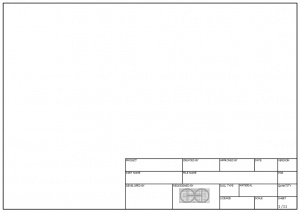
The established formats must be used. | |||
[[File:blueprint format1.jpg|thumb|<small>'''[[Media:Blueprint_format1_doc.pdf|Format for application]]'''</small>]] | |||
[[File:blueprint format2.jpg|thumb|<small>'''[[Media:Blueprint_format2_doc.pdf|Format for Part list]]'''</small>]] | |||
The content of the application form must be written in English and must contain the following fields: | |||
*PROJECT -> Name of the Project established or approved by OHO. | |||
*CREATED BY -> abbreviation of the full name and surname of the developer (e.g. M. Serrantes). | |||
*APPROVED BY -> abbreviation of the full name and surname of the director, e.g. D. Jaeger. | |||
*PART NAME -> Name of the previously defined part or assembly, in case of the sheet for [[Stuecklisten]], enter Part List. | |||
*PART CODE -> Part Code, already defined in the [[Stuecklisten]]. | |||
*DOCUMENT TYPE -> Depending on the content of the sheet, it can be: "PART" "ASSEMBLY" or "PARTS LIST". | |||
*MATERIAL -> Indicate the material of the part, usually Steel C45, Steel A36. | |||
*LICENCE -> Specify the license of the project, established or approved by OHO, e.g. "CERN-OHL". | |||
*FILE NAME -> Filename of the part or assembly present in the sheet. | |||
*VERSION -> Version number of the project, the first version is 1.0. | |||
*QUANTITY -> Total quantity of the part or assembly in the sheet, within the complete assembly. | |||
*SCALE -> Scale used by default in the sheet, specify in views if there are enlargements. | |||
*SHEET -> Number of the sheet in the complete pdf in sheet/sheet format. | |||
*DATE -> Date of last edition. | |||
*DEVELOPED BY -> Organisation that developed the project, may include logo. | |||
*REDESIGNED BY -> In case there are modifications in the design, place [https://opensourceecology.de/ OSEG] and your logo. | |||
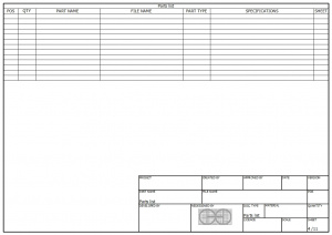
The sheet corresponding to the 'Part List' contains the same fields already defined in the [[Stuecklisten]] of the Project, with the following exceptions: | |||
*The 'PART CODE' field is replaced by 'FILE NAME'. | |||
*The 'SHEET' column is included. | |||
*The lines corresponding to each page of the Technical Notes section are included. | |||
Version vom 9. März 2021, 02:46 Uhr
The process of drawing up the plans is preferably carried out in the same program in which the CAD models were created (Inventor, SolidWorks, AutoCAD...). In this program, a drawing file [.idw or similar] must be created, from which the following pdf files must be generated:
General Pages
General Assembly Views
Here the project is represented in its entirety, using the appropriate scale, it includes orthogonal views, isometries, section views, detail views, general dimensions, weld details, among others, that show aspects of the assembly of the equipment in general. These views can span multiple pages, depending on the degree of complexity of the project.This section is identified with the code A1.
Single view of general explosion
On one page, the project's main assemblies should be displayed, separated and aligned according to their assembly logic, in an isometric view.Certain common components, such as screws, pipes, connecting elements, among others, may remain in the first level of the assembly or belong to the most important set with which they are related.This section is identified with the code A2.
Complete part list.
In the same format as the Technical Drawings, a table must be added with the information of all the parts and assemblies, according to their hierarchical order.all fields must be filled according to the instructions explained below.It can span as many pages as necessary.This section is identified with the code B1, B2 ..., for each page.
Technical Notes
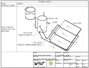
It includes all information of technical relevance, which is not practical to represent in the plans, depending on the Project, it can show the following aspects:
- Technical notes
- General technical notes
- Standards
- Hydraulic scheme
- Electrical plan
- Printed circuit board PCB
- Software
- Programmable logic controller (PLC)
- Civil engineering
- Others that are considered necessary.
This section is identified with the code C1, C2 ..., for each page.
Parts and Assemblies
Views of main assemblies or sub-assemblies
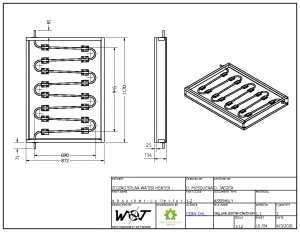
For each main assembly, general views of the assembly must be included, using the appropriate scale, including orthogonal views, isometries, section views, detail views, general dimensions, weld details, among others, that show aspects of the assembly's manufacture. These views can span multiple pages, depending on how complex the set is.This section is identified with the code corresponding to the set: 1, 2, 3 ...or 1.x, 2.x, 3.x for projects with more degrees of hierarchy.
Single explode view for main assemblies or sub-assemblies (if applicable)
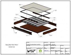
For each set that requires more details, in addition to those indicated its views or that has some degree of complexity, a page must be included with its parts separated and aligned according to its assembly logic, in an isometric view.This section is identified with the code corresponding to the set: 1, 2, 3 ...or 1.x, 2.x, 3.x for projects with more degrees of hierarchy.
Views of parts or pieces
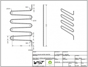
For the most basic levels of hierarchy, part drawings should be included with all the dimensions required for their manufacture, including orthogonal views, isometries, section views, detail views, dimensional tolerances (if applicable), surface quality symbols (if applicable).
Additional Notes
In the Technical Drawings, standard parts are not included. View sheets may include orthogonal views, isometric views, cuts, details, annotations, etc. The established formats must be used.
The content of the application form must be written in English and must contain the following fields:
- PROJECT -> Name of the Project established or approved by OHO.
- CREATED BY -> abbreviation of the full name and surname of the developer (e.g. M. Serrantes).
- APPROVED BY -> abbreviation of the full name and surname of the director, e.g. D. Jaeger.
- PART NAME -> Name of the previously defined part or assembly, in case of the sheet for Stuecklisten, enter Part List.
- PART CODE -> Part Code, already defined in the Stuecklisten.
- DOCUMENT TYPE -> Depending on the content of the sheet, it can be: "PART" "ASSEMBLY" or "PARTS LIST".
- MATERIAL -> Indicate the material of the part, usually Steel C45, Steel A36.
- LICENCE -> Specify the license of the project, established or approved by OHO, e.g. "CERN-OHL".
- FILE NAME -> Filename of the part or assembly present in the sheet.
- VERSION -> Version number of the project, the first version is 1.0.
- QUANTITY -> Total quantity of the part or assembly in the sheet, within the complete assembly.
- SCALE -> Scale used by default in the sheet, specify in views if there are enlargements.
- SHEET -> Number of the sheet in the complete pdf in sheet/sheet format.
- DATE -> Date of last edition.
- DEVELOPED BY -> Organisation that developed the project, may include logo.
- REDESIGNED BY -> In case there are modifications in the design, place OSEG and your logo.
The sheet corresponding to the 'Part List' contains the same fields already defined in the Stuecklisten of the Project, with the following exceptions:
- The 'PART CODE' field is replaced by 'FILE NAME'.
- The 'SHEET' column is included.
- The lines corresponding to each page of the Technical Notes section are included.

